



The following installation procedures are installation guidelines for a Thermon electric heat tracing system. For translations other than English and the local language translation provided here, please contact Thermon. The English language installation procedures shall govern.
Installation must comply with Thermon requirements and be performed in accordance with EN-IEC 60079-14 and EN-IEC 60079-30-2 standards for hazardous areas (if applicable) and all other applicable national and local electrical codes.
Individuals installing these products are responsible for complying with all applicable health and safety regulations. Proper personal protective equipment (PPE) must be used during installation. Contact Thermon if you have additional questions.
Applications . . .
- Electric heat tracing cables are used for freeze protection or temperature maintenance on piping, tanks, and instrumentation. These instructions are intended for typical piping applications. For tank and instrumentation installation details, refer to the Installation Guides on our website at thermon.com.
- Heat tracing cables may be installed in ordinary (unclassified) and hazardous (classified) areas depending on specific cable options and approvals.
Field Practice . . .
- Provide protective clothing and other safety equipment necessary to isolate personnel from potential arc flash and shock hazards identified in the analysis.
- Train personnel on the purpose/function of the electric heat tracing system, electrical power supply/control equipment, and how to recognize and prevent hazards that may arise during operation and maintenance.
- Prior to installation or servicing:
- Identify the circuit or equipment to be disconnected and all potential sources supplying electrical energy to that specific circuit or equipment.
- Disconnect power from all supply circuits prior to installation or servicing.
- Lockout/tagout devices according to established procedures.
- Visually verify that circuit disconnecting devices are in the open position before connecting the electrical cable to the heat tracers.
- Test for the absence of voltage using an approved voltmeter (verify the voltmeter on a known voltage source immediately before and after testing).
- Use temporary jumper cables rated for fault duty between each supply conductor and ground to protect against accidental re-energization of supply conductors.
Complete Electric Heat Tracing System . . .
A complete electric heat tracing system suitable for use may include the following components:
- Electric heat tracing cable (self-regulating, power-limiting, parallel constant watt, or series constant watt).
- Power connection kit
- RTD sensor or control thermostat.
- In-line/T-splice kit (allows joining of two or three cables together).
- Cable termination 5a. Circuit light end kit.
- Attachment tape (use at 30 cm intervals or as required by codes or specifications).
- “Electric Heat Tracing” label (peel-and-stick label applied to the insulation vapor barrier at 3 m intervals or as required by codes or specifications).
- Thermal insulation and vapor barrier (supplied by others).
The absence of any of these items may result in system failure and create a safety hazard.
Notes . . .
- Refer to the specification sheet for cable types and approvals.
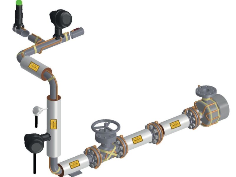
- Illustration shows a typical self-regulating heating circuit.
- Temperature control is recommended for all freeze protection and temperature maintenance heat tracing applications.
- All heat-traced lines must be thermally insulated.
- Refer to Thermon Form PN50273U-T for MI heating cable installation instructions.
Figure A: Typical Heat Tracing Installation

Upon Receiving Cable . . .
- Upon receiving the heating cable, inspect it to ensure the correct type and output capacity have been received. All flexible cables have the catalog number, voltage rating, and watt output printed on the outer jacket.
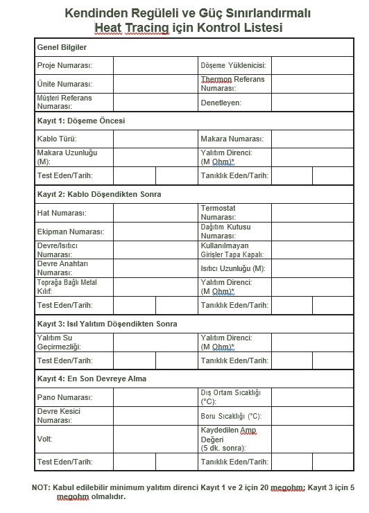
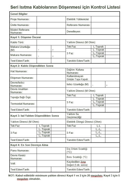
- Visually inspect the cable for any damage during transit. The heating cable must be tested with a megohmmeter at a minimum of 500 Vdc to verify electrical integrity between the heating cable bus wires and metallic braid. The recommended test voltage for polymer-insulated heating cables per IEEE 515 and EN-IEC 60079-30 is 2500 Vdc. Minimum resistance must be 20 megohms. Connect the positive lead of the megohmmeter to the cable bus wires and the negative lead to the metallic braid. (Insulation Resistance Test Pages 9 & 10 – Record 1)
- Store in a dry location. Keep the ends of trace heaters and kit components dry prior to and during installation.
Prior to Installing Cable . . .
- Ensure all piping and equipment to be heat traced is completely installed and pressure tested.
- Surface areas where heat tracing is to be installed must be thoroughly clean. Remove dirt, rust, and scale with a wire brush; remove oil and grease films with a suitable solvent.
Initial Installation . . .
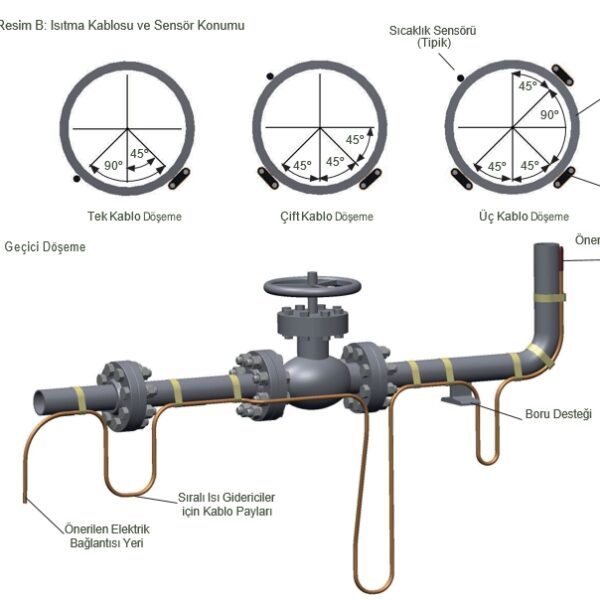
- Install the cable on the lower quadrant of the pipe at the 4 or 8 o’clock position. If access is an issue, the cable may be installed at the 10 or 2 o’clock position. The temperature sensor should be located at least 90° away from all heating cables. Refer to Figure B for Heating Cable and Sensor Position.
- Begin temporary installation at the recommended end of circuit location and lay out the heating circuit on the pipe to allow extra cable for power connection and any splice locations. Refer to Figure C for temporary installation.
- Allow additional cable allowances for valves, flanges, elbows, and supports in accordance with the figures in these installation procedures and tables on pages 5 and 6.

Installation on Elbows, Supports, and Flanges
Installation on Elbows, Supports, and Flanges . . .
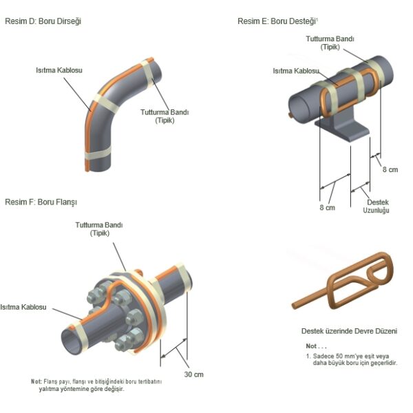
- Install the heating cable according to Figures D, E, and F below. Secure the heating cable to the piping with attachment tape.
- Elbows: Locate the cable on the outside radius of the elbow to supply sufficient heat to compensate for the additional piping material. Secure the cable to the elbow with attachment tape on both sides.
- Pipe Supports: Insulated pipe supports require no additional heating cable. For non-insulated supports, allow an additional 40 cm of heating cable plus twice the length of the pipe support.
- Flanges: Loop the cable around the pipe on both sides and close to the flange. The heating cable must maintain contact with the flange as it wraps around the pipe flanges to compensate for additional heat loss.
- Refer to the product specification sheet for minimum bend radius requirements for the specific cable type. Do not exceed minimum bend radius when completing installation.
Installation on Valves and Pumps .
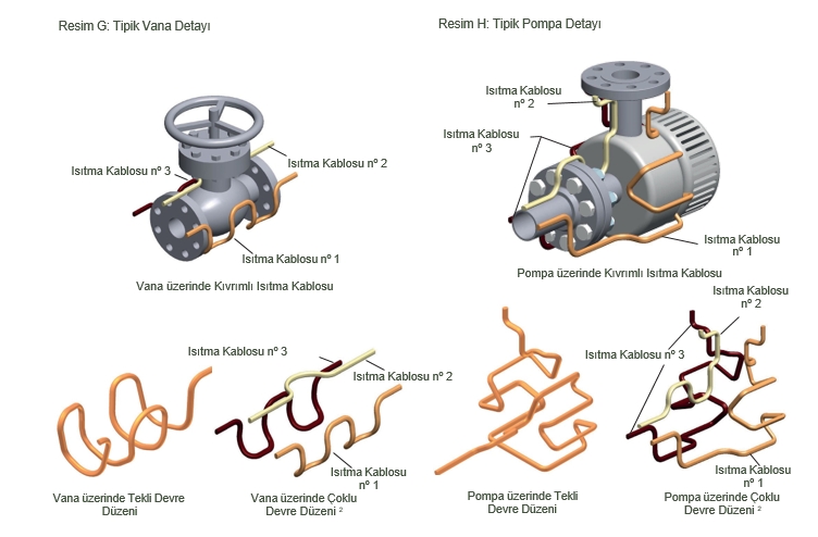
- Install the heating cable according to Figures G and H below. Secure the heating cable to the piping with attachment tape.
- Valves, pumps, and other equipment require extra cable to supply additional heat to compensate for the increased heat loss caused by these items. Refer to Table 1 for estimated cable requirements for typical valve and pump installations. The allowance shown in Table 1 is for 68 kg valves. Heavier valves require additional cable. Refer to the heat trace isometric drawing for project-specific allowances.
- Loop the heating cable onto valves and pumps using the looping technique (this permits removal of the valve or pump if necessary). Constant watt heating cable must not overlap itself.
- Refer to the product specification sheet for minimum bend radius requirements for the specific cable type. Do not exceed minimum bend radius when completing installation.


Circuit Protection Requirements . . .
- Overcurrent protection (typically circuit breakers) for each branch circuit. This protection must isolate all power conductors from the supply source.
- Ground fault equipment protection for each circuit. For typical installations (with TT and TN grounding systems), a means of protection against ground faults incorporating a residual current device for each branch circuit is required. A minimum mA trip level is recommended for fixed-level ground fault circuit interrupters. For adjustable devices, the preferred trip level is 30 mA above the inherent capacitive leakage specified by the heat tracing supplier. Where maintenance and supervision conditions ensure that only qualified personnel service the installed systems and continuous circuit operation is required for safe equipment or process operation, ground fault detection without de-energization is acceptable provided an alarm gives a recognized response.
- For IT grounding systems, a protection device incorporating an electrical insulation monitoring device that disconnects the power supply whenever electrical resistance drops below 50 ohms/volt of nominal voltage is required to protect against ground faults.
Thermal Insulation . . .
- Prior to installing thermal insulation, perform an insulation resistance test. The cable must be tested with a test voltage of at least 500 Vdc. However, for polymer-insulated heating cables, 2,500 Vdc is recommended. The minimum acceptable level shall be no less than 20 megohms.
- The necessity of properly installed and well-maintained thermal insulation cannot be overemphasized. Without insulation, heat losses are typically too high to be compensated for by a conventional heat tracing system.
- In addition to piping and in-line equipment like pumps and valves, all heat sinks must also be properly insulated. These include pipe supports, hangers, flanges, and in many cases, valve bonnets.
- Regardless of the type or thickness of insulation used, a protective barrier must be installed. This barrier protects the insulation from moisture ingress and physical damage, helping the heat tracing system function properly. Seal all penetrations through the thermal insulation.
- Apply an “Electric Heat Tracing Caution” label to the insulation vapor barrier and to serviceable equipment at 3 m intervals or as required by codes or specifications. Labels are supplied with Thermon products.
Final Inspection and Documentation . . .
- After thermal insulation and weather barrier are installed, but BEFORE ENERGIZING THE HEATING CIRCUIT, repeat the insulation resistance test. This test should identify any heating cable damage that may have occurred during insulation installation. (Insulation Resistance Test Pages 9 & 10 – Record 3)
For Series Heating Cables, measure electrical loop resistance and record the measured Ohm value (Page 10 – Record 3.) - It is recommended to temporarily energize the circuit and record volts, amperes, pipe temperature, and ambient temperature. Take readings 5 minutes after energizing. This information can be valuable for future reference and retained for a historical operating data log. (Insulation Resistance Test Pages 9 & 10 – Record 4)
- A stabilized design may be used without a limiting device for self-regulating, power-limiting, and constant watt heating cables to determine T-class rating using Thermon CompuTrace software or Thermon Engineering.
- Series heating cable output and T-rating depend on supply voltage, cable resistance, temperature conditions, as well as additional variables accounted for through the use of Thermon CompuTrace software or Thermon Engineering.
- Maximum temperatures provided by Thermon CompuTrace software and Thermon Engineering are calculated according to EN-IEC 62086-2 and EN-IEC 60079-30 methods and requirements.
- If a stabilized design is used, the end user must record system parameters and area T-class, maintaining these records for as long as the heating cable is operational.
- Test the system at regular intervals, at least once a year. Record all information after performing testing. If the system fails any test, refer to Thermon Maintenance & Troubleshooting Guide for assistance. Disconnect power to affected circuits and make necessary repairs immediately.
- If a maximum control device is provided to limit the T-rating for circuit design, verify the maximum setting on the device to ensure it limits maximum surface temperature in compliance with clause 4.3 of EN-IEC 60079-0 code.
Maintenance and Repair . . .
- Refer to Form TEP0066T-Electric Heat Tracing Maintenance and Troubleshooting Guide.
Cable Test Report
- Refer to these Installation Procedures for general installation procedures, requirements, and guidelines.
- Upon receiving the heating cable, inspect it to ensure the correct type and output capacity have been received. All flexible cables have the catalog number, voltage rating, and watt output printed on the outer jacket.
- Visually inspect the cable for any damage during transit. The heating cable must be tested with a megohmmeter at a minimum of 500 Vdc to verify electrical integrity between the heating cable bus wires and metallic braid. The recommended test voltage for polymer-insulated heating cables per IEEE 515 and EN-IEC 60079-30 is 2500 Vdc. Minimum resistance must be 20 megohms.
(Insulation Resistance Test Pages 9 & 10 – Record 1)- Connect the positive lead of the megohmmeter to the cable bus wires.
- Connect the negative lead of the megohmmeter to the metallic braid.
- Energize the megohmmeter and take the reading; readings between 20 megohms and infinity are acceptable results. Readings below 20 megohms may indicate that the electrical insulation on the polymer-insulated heat trace is damaged. Recheck the heating cable for physical damage between the braid and heating element; minor cuts or scuffs on the outer jacket will not affect the megohmmeter reading as long as there is no actual penetration through the braid and non-conductive insulation jacket.
- After completion of installation but prior to thermal insulation installation, re-inspect the heating cable to ensure there is at least 500 Vdc megohmmeter resistance between the heating cable bus wires and metallic braid. Recommended test voltage for polymer-insulated heating cables per IEEE 515 and EN-IEC 60079-30 is 2500 Vdc. Minimum resistance must be 20 megohms. (Insulation Resistance Test Pages 9 & 10 – Record 2)
- After thermal insulation is installed, repeat the insulation resistance test. Minimum resistance must be 5 megohms. (Insulation Resistance Test Pages 9 & 10 – Record 3) For Series Heating Cables, measure electrical loop resistance and record the measured Ohm value (Page 10 – Record 3.)
- After thermal insulation is installed and power supply connection is completed, record panel and circuit breaker information. Ensure all junction boxes, temperature controllers, cable seals, etc., are properly secured. Set temperature controller (if present) to manual setting and apply nominal voltage to heat tracing circuit(s) for 5 minutes. Record ambient temperature, measure and record circuit voltage and electrical current. (Insulation Resistance Test Pages 9 & 10 – Record 4)
NOTE: Testing procedures outlined in this booklet must be completed on installed heating cables during installation to maintain warranty.
For additional product information regarding Thermon heating cables, refer to individual product specification sheets.
BSX™ (see Form TEP0067U-T) RSX™ 15 (see Form TEP0048U-T) HTSX™ (see Form TEP0074U-T) KSX™ (see Form TEP0072U-T) VSX™ (see Form TEP0008U-T) HPT™ (see Form TEP0011U-T) FP (see Form TEP0016U-T) HTEK™ (see Form TEP0022U-T) TEK™ (see Form TEP0021U-T) TESH™ (see Form TEP0070U-T)